|
Product Series: IC |
Article No: FAQ075 |
IC650 – DC Output
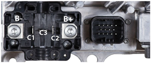
WARNING: Be careful not to allow battery voltage to be applied to the blade terminals (C1, C2, C3), as it will result in permanent damage to the charger.
| Pin |
Minimum Recommended Wire Size (AWG/mm2) |
Description | Notes |
| - | 12/4.0 | Battery negative | Each accepts a 1/4” or larger ring terminal Fastener: Torx T30 screw, M6 nut. Recommended Torque: 4.5Nm +/-5% |
| + | 12/4.0 | Battery positive | |
| C1 | 20/0.5 | Battery temperature sense negative | Each is a 1/4” quick-connect terminal. |
| C2 | 20/0.5 | Battery temperature sense positive | |
| C3 | 20/0.5 | Interlock Signal | 1/4” quick-connect terminal; normally closed to battery positive. Open when the charger output is active. 1.5A max. |
In most cases; the temperature sensor (White cable, Thermistor) is attached to battery negative wire (Black Wire, B-). The wires are separated at the other end where they connect to the DC terminals of the IC series. Black wire should be connected to B- terminal and White wire connected to C2 terminal. Red wire goes to DC positive terminal (B+) and Green wire is intended for the interlock (C3 Terminal).
If you see a different cable configuration, please contact the manufacturer of your vehicle or place of purchase as they will know best what they provided you.
IC900/1200 – DC Output

WARNING: Be careful not to allow battery voltage to be applied to the blade terminals (L1, L2, C1, C2, C3, F+, F-), as it will result in permanent damage to the charger.
| Pin |
Minimum Recommended Wire Size (AWG/mm2) |
Description | Notes |
| - | 12/4.0 (IC900) 10/6.0 (IC1200-24V) 14/2.5 (IC1200-36V, 48V) |
Battery negative | Each accepts a 1/4” or larger ring terminal Fastener: Torx T30 screw, M6 nut Recommended torque: 4.5Nm +/-5% |
| + | Battery positive | ||
| L1 | 22/0.5 (2-conductor cable) |
Remote LED red anode/green cathode | Each is a 1/4” quick-connect terminal. L2 goes high with respect to L1 to light the remote LED green, and vice versa to light the remote LED red. |
| L2 | Remote LED green anode/red cathode | ||
| C1 | 18/1.0 (2-conductor cable) |
Battery temperature sense negative | Each is a 1/4” quick-connect terminal. |
| C2 | Battery temperature sense positive | ||
| C3 | 12/4.0 | Interlock Signal | 1/4” quick-connect terminal; normally closed to battery positive. Open when the charger output is active. |
| F+ | N/A | Fan power/control; 0-12 VDC (IC1200 only) | 1/4” quick-connect terminals |
| F- | Fan power/control return; 0-12 VDC (IC1200 only) |
In most cases; the temperature sensor (White cable, Thermistor) is attached to battery negative wire (Black Wire, B-). The wires are separated at the other end where they connect to the DC terminals of the IC series. Black wire should be connected to B- terminal and White wire connected to C2 terminal. Red wire goes to DC positive terminal (B+) and Green wire is intended for the interlock (C3 Terminal).
If you see a different cable configuration, please contact the manufacturer of your vehicle or place of purchase as they will know best what they provided you.